Suspension Arms
Overview
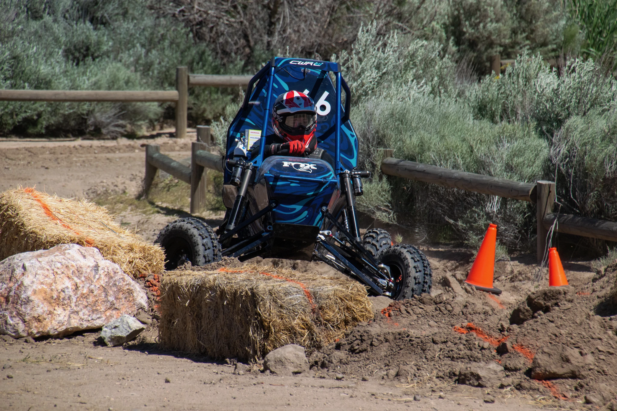
I designed all three of the 2024 car’s suspension arms and assisted with the 2025 arms. The suspension arms connect the frame of the car to the wheel and the shock absorber mounts along these arms (see image below). They see pretty extreme loads since they have to hold the wheels on the body as the car goes over logs, rocks and jumps. The following is a guide to the process I used.


First Steps
Requirements
- Conform to the suspension geometry design
- I was given the relative position of the connection points of the arm and had to design around them
- Be strong enough to not break in our testing and competitions
- Minimize weight while conforming to the previous requirements
Free Body Diagram
- The diagram to the left helps understand the force in the the arms with shock absorber mounts (front upper and rear)
- As I’ll explain in the analysis section peak loading is at the limit of the shock absorber travel, so the region of the arm past the shock absorber is effectively a cantilevered beam with the base at the shock
- The front lower arm in SR24 (2024 vehicle) doesn’t have a shock absorber mount and as such, it’s primarily loaded in tension and compression (no bending)
Data Collection & Analysis
Data Collection
- To understand the peak forces distributed through each outboard assembly (front and rear) we put a wheel force transducer on a previous car and tested it over obstacles similar to what we compete with
- This is a standard sensor used in the automotive industry
- After testing, we processed the data to find the peak forces and moments in each direction which would inform analysis for every outboard component
Analysis
- Since we were unable to gather the position of the suspension for the peak loading of the wheel force transducer, we were forced to make the conservative estimate that peak loading occurred at “bump stops” – the limit of the shock absorber travel
- This means that the shock absorber is effectively a steel rod, which loads the arms a lot
- Additionally, in order to properly model the force split as the system deforms, an assembly level simulation of the entire outboard system is the most accurate
- I setup and ran the rear outboard assembly FEA for both SR24 and SR25
- This simulation is shown to the right and is as described above, at bump-stops with the peak wheel force found in our data collection
- For SR24’s front arms, we were unable to get the full front outboard assembly to solve properly in Ansys before the deadline for the arms so we relied on part level simulations with conservative estimates of the force split.
- Using the stress results of this analysis, I was able to optimize the tab structure of each of the arms to distribute forces and minimize weight
Wheel force transducer testing

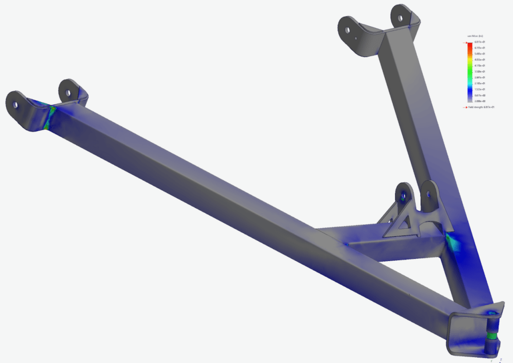

FEA on suspension arm concepts
Performance
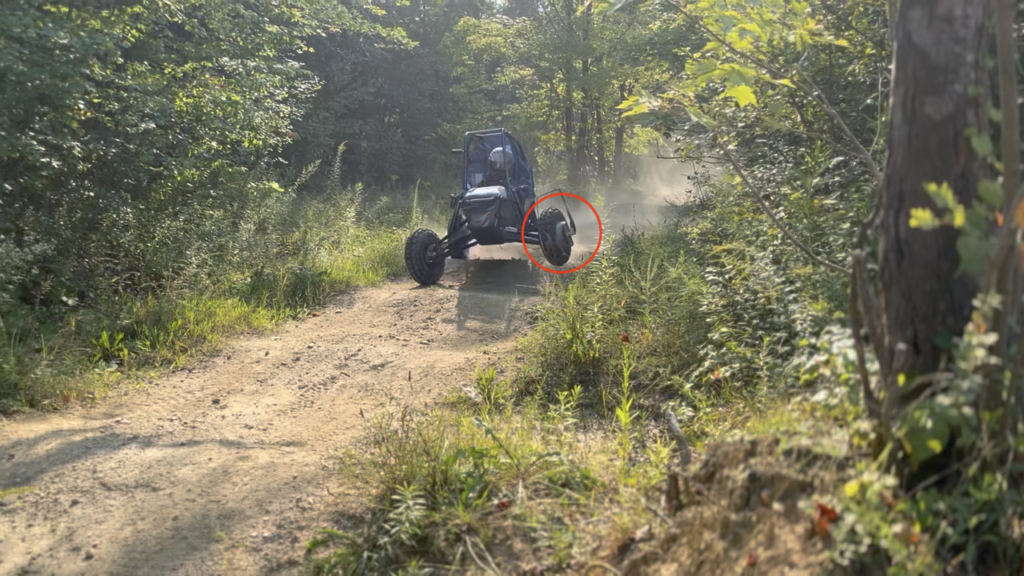
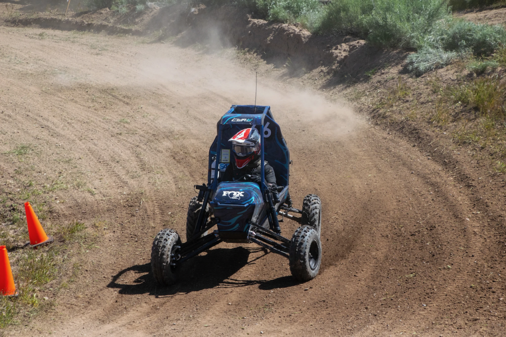
- In the 2024 season, all three suspension arms (front upper, front lower, and rear) saw no critical failures over all of our testing and three competitions
- We did see yielding in the front arms over extended periods of use. This is likely since we had to make so many assumptions about the forces in the arms and were unable to perform proper fatigue analysis on the front outboard assembly (we are actively working on this for future cars).